Fan Powered Systems
Fan Powered Filter Systems
-
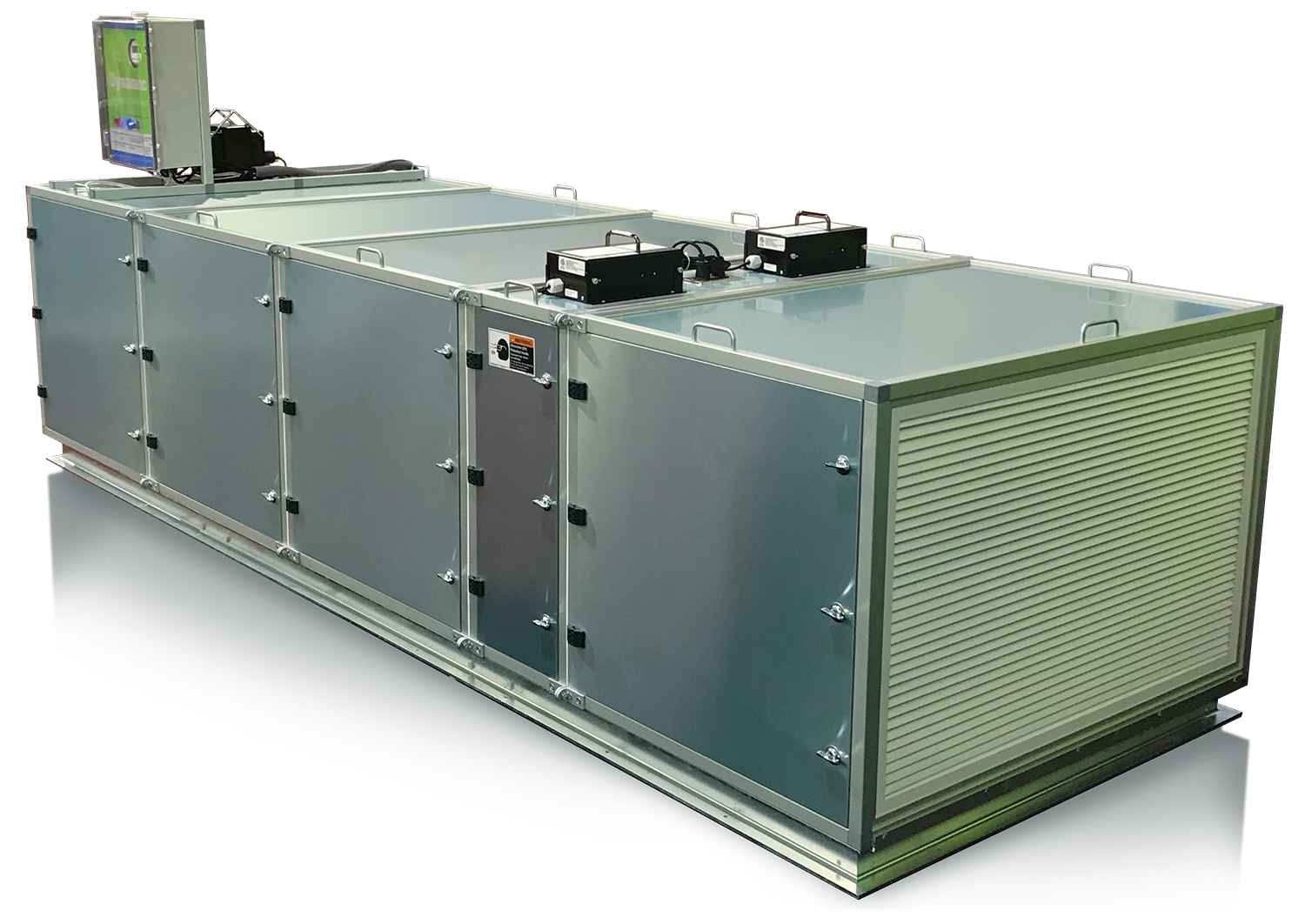
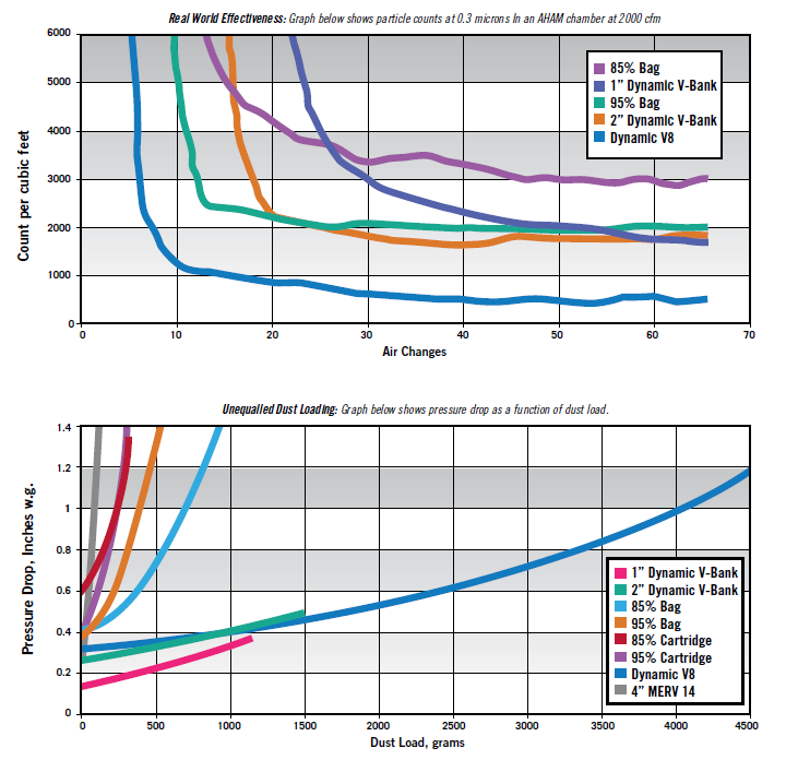
Dynamic offers a full line of commercial air cleaning equipment with benefits beyond traditional filtration, such as MERV 15 performance, lower energy and operating costs, and the mitigation of odors and VOCs.
Dynamic Fan Powered Filter Systems can be configured with:
- Dynamic Polarized-Media Air Cleaners
- Dynamic V8® Air Cleaning Systems
- Dynamic Sterile Sweep® Germicidal UVC Systems
- Dynamic Activated Carbon Matrix (ACM) Systems
-
For those who are serious about theimportance of Air Filtration and Odor Mitigation
- A comprehensive, scalable “total” solution for a wide variety of applications.
- Fast, easy installation.
- Provides ongoing energy savings and long maintenance cycles.
- Modular components can be tailored to address specific IAQ needs.
- 120/240 VAC power.
- ECM (electronically commutated) motor, for very fine speed control, high efficiency at full speed, and dramatic reduction in power usage at low speeds.
- Standard 10 speed digital controller for simple airflow adjustment.
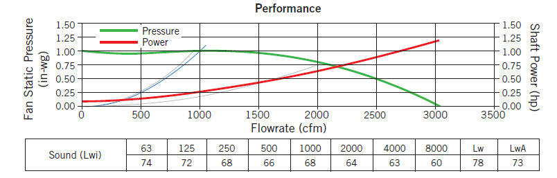
- Airflow capability up to 3,000 CFM (with larger fan/motor).
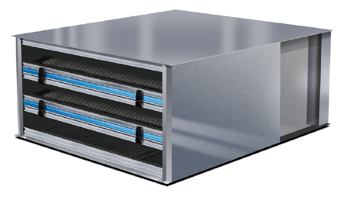
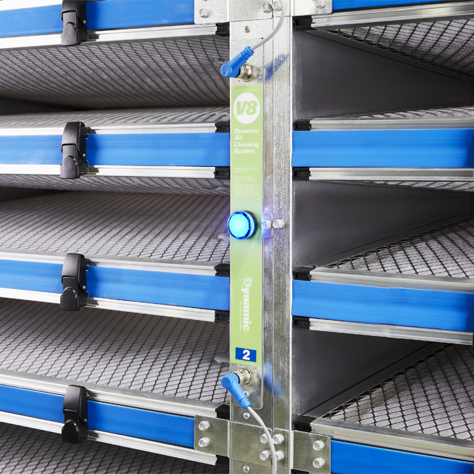
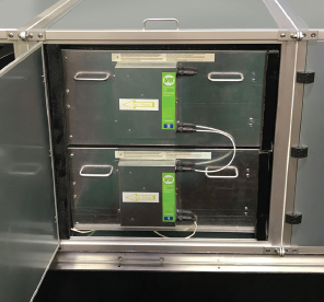
 Air Cleaner Modules mount to vertical posts (provided) and stack in the filter section like Legos. Module to Module seals are made with extrusion strips and seal brackets (provided). Pre-filters are generally not needed.
 Dynamic V8s mount to rectangular vertical posts in the AHU. These are 1” wide and are attached to the ceiling and floor of the AHU. Posts are provided and are fabricated to the specifics of the AHU.
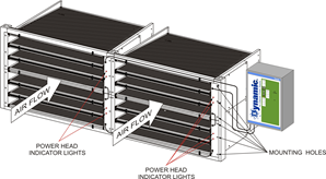
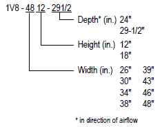
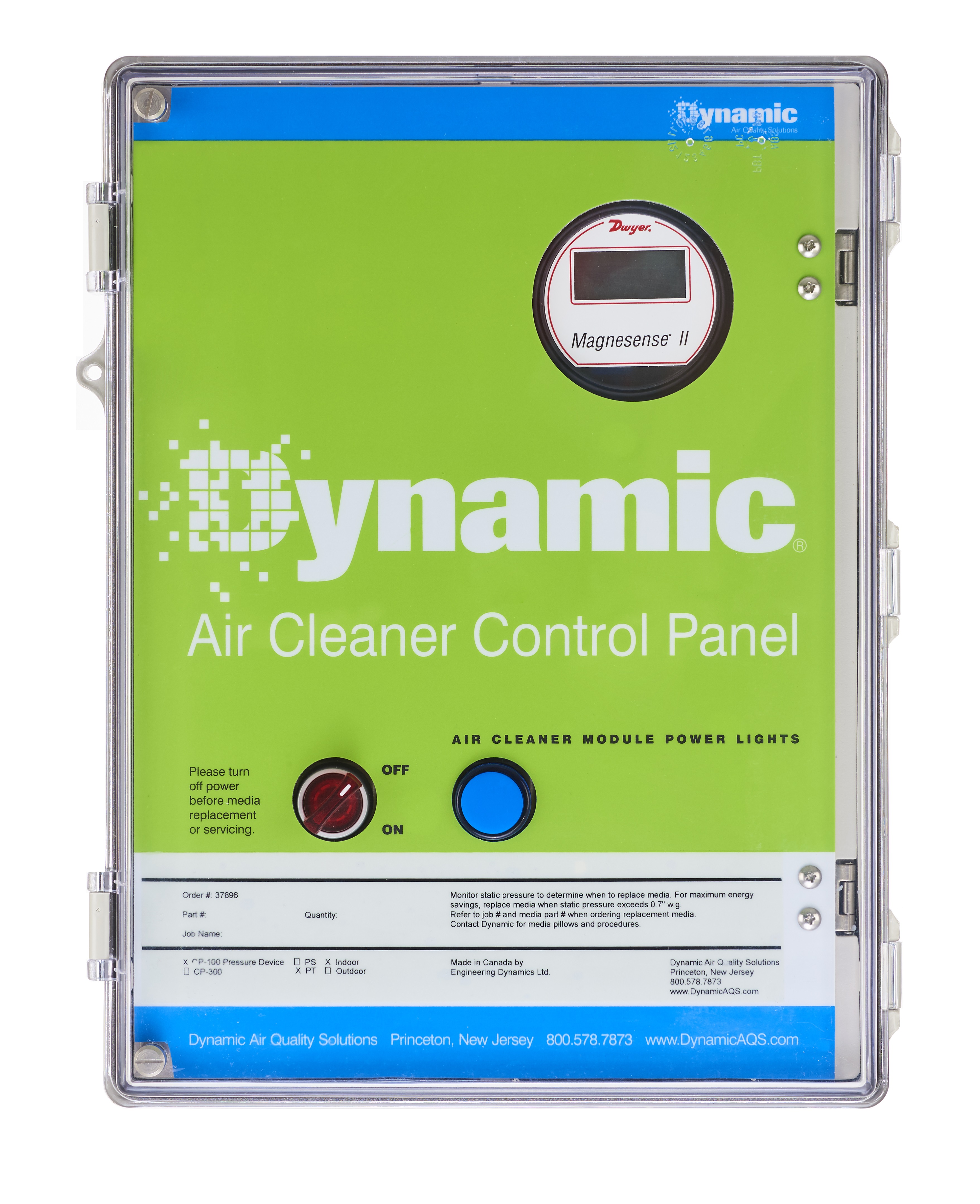 The V8 Modules require 24VAC. An 18” Module draws 6va @ 24vac and a 12” Module draws 3va @24vac. The Dynamic Control Panel takes line voltage of 120/208/240/480V single-phase only, and outputs 24vac. Powering Dynamic V8s, for up to a 300,000 cfm AHU, should only require a single 15A circuit. The Control Panel provides Return Indicating lights, necessary breakers, disconnect switch and several differential pressure gauge options. The Control Panel is 16”x12”x6.5” and typically mounts adjacent to the access door of the AHU. Control Panels are available rated for indoor or outdoor use.
 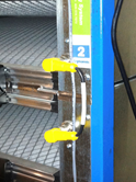 Supply wires run from the Control Panel to the Modules as shown in the submittal. Modules are wired together, one to the next, with the supplied jumpers. Return wires run back from the Air Cleaner column to the Control Panel to show power throughout the column. Door interlock switches to de-energize the Air Cleaners are required and supplied. These break the 24vac circuit and not the line voltage. While each Dynamic V8 runs at 9kV, it is at very low current and there are no exposed live parts.