For Dynamic V8 Air Cleaning System selection and configuration in a typical AHU installation.
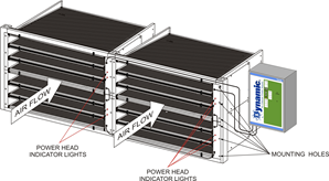
Shown above: Four Dynamic V8 Modules with Control Panel
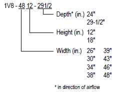
Configurations and Sizes
 Air Cleaner Modules mount to vertical posts (provided) and stack in the filter section like Legos. Module to Module seals are made with extrusion strips and seal brackets (provided). Pre-filters are generally not needed.
Module width is chosen to minimize the overall number of Modules and keep them the same width in each AHU. This simplifies media replacement and ordering. Each Module is numbered and installed according to the submittal.
Example, if the filter section is 106” wide and 82” tall: the configuration is three 34” wide Module columns across, for a total width of 102”. Each column is comprised of three 18”H Modules and two 12”H Modules, for a total height of 78”. Once installed, the Modules are flashed and sealed to the walls of the AHU. The bottom row will have a 1.625” footer and the top row will have a 1.50” header to facilitate sealing in the AHU. This 3.125” must be added to the overall combined height of the Modules when configuring.
Mounting Options
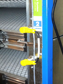
 Dynamic V8s mount to rectangular vertical posts in the AHU. These are 1” wide and are attached to the ceiling and floor of the AHU. Posts are provided and are fabricated to the specifics of the AHU.
Access and Service Space Requirements
For Modules 29.5” Deep: An additional 24” of space, in direction of airflow, is required for media replacement. This service access can be upstream or downstream of the Air Cleaners.
For Modules 24” Deep: An additional 18” of space, in direction of airflow, is required for media replacement. This service access can be upstream or downstream of the Air Cleaners.
Access is most often through a mixing box, pre-filter section, or coil access section. Dynamic V8 Media Pads are directional, and the system must be ordered as “downstream access” if needed. If Modules are to be installed through access doors, it is important to make sure the door is wide enough for the Modules, e.g. an 18” Module won’t fit through a 16” door.
Electrical Installation and Requirements
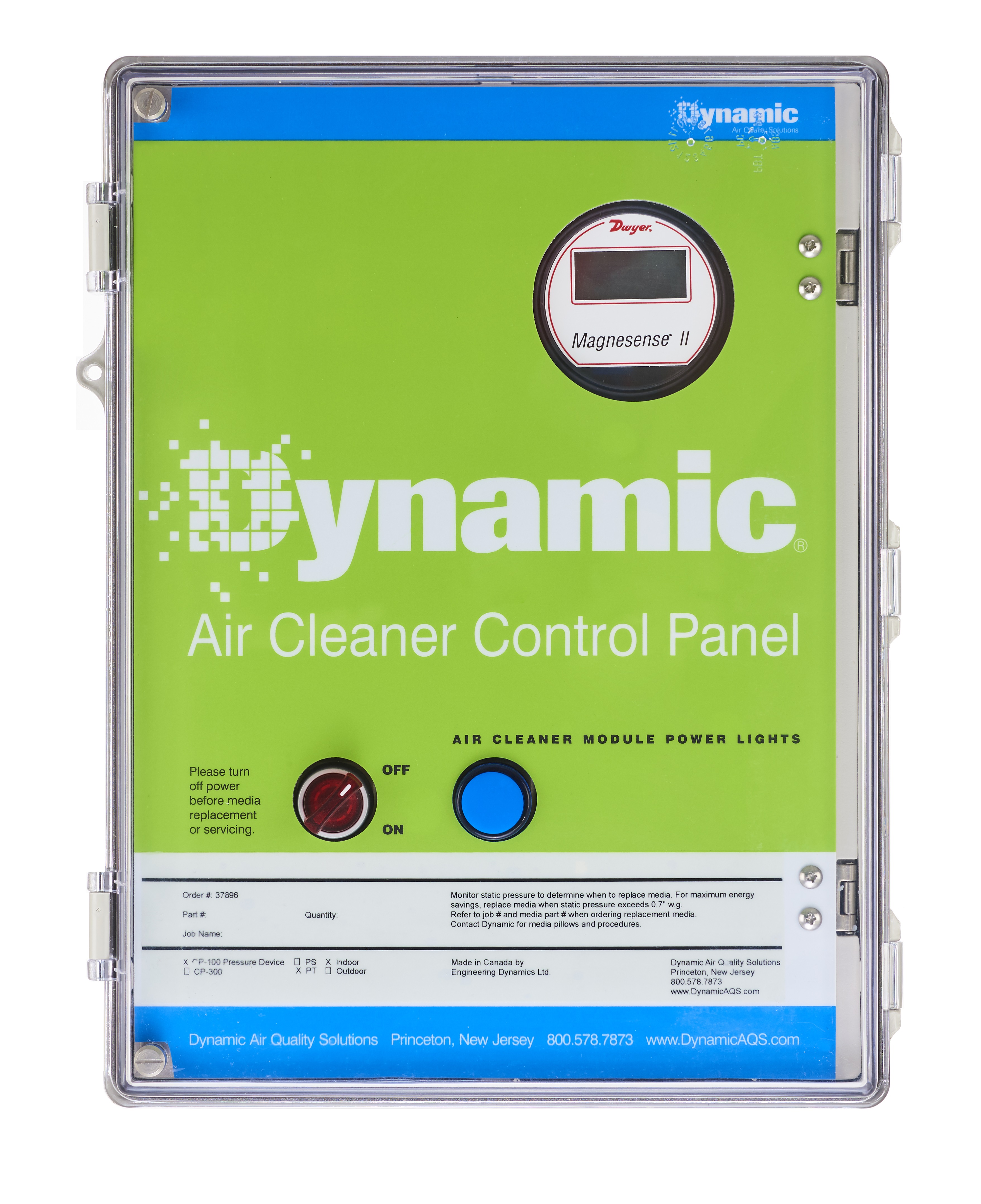 The V8 Modules require 24VAC. An 18” Module draws 6va @ 24vac and a 12” Module draws 3va @24vac. The Dynamic Control Panel takes line voltage of 120/208/240/480V single-phase only, and outputs 24vac. Powering Dynamic V8s, for up to a 300,000 cfm AHU, should only require a single 15A circuit. The Control Panel provides Return Indicating lights, necessary breakers, disconnect switch and several differential pressure gauge options. The Control Panel is 16”x12”x6.5” and typically mounts adjacent to the access door of the AHU. Control Panels are available rated for indoor or outdoor use.
 Supply wires run from the Control Panel to the Modules as shown in the submittal. Modules are wired together, one to the next, with the supplied jumpers. Return wires run back from the Air Cleaner column to the Control Panel to show power throughout the column. Door interlock switches to de-energize the Air Cleaners are required and supplied. These break the 24vac circuit and not the line voltage. While each Dynamic V8 runs at 9kV, it is at very low current and there are no exposed live parts.
In the example above, there are nine 18” Modules and six 12” Modules. The total electrical draw would be 72va and a 100va Control Panel would be used. Control Panels are available up to 300va.
General Specifications
Pressure drop: of a typical Dynamic V8 bank @ 500fpm: ~0.28” w.g.
Weight: 18” modules = ~2.5lbs/inch of width; 12” modules = ~1.7lbs/inch of width
Other Configurations
24” Deep modules: these are identical in application to the 29.5” modules and are used when there are space constraints. They have proportionally higher pressure drop and less dust holding capacity.
V8-SL Side Access modules: these are 24” or 29.5” in depth and have a stacking, self-supporting racking system that allows them to be installed and accessed from the side; for applications with no in-unit service access, such as in a rooftop unit. V8-SL Modules are not available in 46” or 48” widths.
VRF and Fan coil modules; these are essentially V8 Modules with a top and a bottom that become sections of duct and are used with equipment with little or no space for filtration. Module enclosures are also available in insulated and uninsulated versions with options for flat or angle filter racks.